有关模块学习的资料已经整理后上传了:
https://wws.lanzoui.com/izIHArp85pa
密码:ayr4
模块介绍
VL53L0是一款意法半导体推出的激光测距模块
果然还是复制官方的说法比较靠谱:
以下内容来自数据手册“Description”和某翻译
The VL53L0X is a new generation Time-of-Flight (ToF) laser-ranging module housed in the smallest package on the market today, providing accurate distance measurement whatever the target reflectances unlike conventional technologies. It can measure absolute distances up to 2m, setting a new benchmark in ranging performance levels, opening the door to various new applications.
VL53L0X是新一代的飞行时间(ToF)激光测距模块,采用当今市场上最小的封装,与传统技术不同,无论目标反射如何,都能提供精确的距离测量。它可以测量高达2米的绝对距离,为性能水平的范围设定了新的基准,为各种新的应用打开了大门。
The VL53L0X integrates a leading-edge SPAD array (Single Photon Avalanche Diodes) and embeds ST’s second generation FlightSenseTM patented technology.
VL53L0X集成了先进的SPAD阵列(单光子雪崩二极管),并嵌入ST的第二代FlightSenseTM专利技术。
The VL53L0X’s 940nm VCSEL emitter (Vertical Cavity Surface-Emitting Laser), is totally invisible to the human eye, coupled with internal physical infrared filters, it enables longer ranging distance, higher immunity to ambient light and better robustness to cover-glass optical cross-talk.
VL53L0X的940nm VCSEL发射器(垂直腔面发射激光器)对人眼完全不可见,再加上内部物理红外滤光片,它可以实现更长的测距距离、更高的环境光免疫力和更好的鲁棒性,以覆盖玻璃光学串扰。
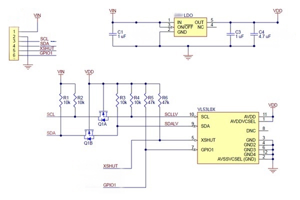
附模块原理图如下:

通信接口及引脚定义
模块采用IIC通信,故:
SCL:IIC时钟线
SDA:IIC数据线
此外:
VIN:电源
GND:接地
XShut:设备唤醒引脚
PS:XShut的接线方法决定了设备的测量模式,引用手册中的说法如下:
There are two options available for device power up/boot.
Option 1:
XSHUT pin connected and controlled from host.This option helps to optimize power consumption as the VL53L0X can be completely powered off when not used, and then woken up through host GPIO (using XSHUT pin).
HW Standby mode is defined as the period when AVDD is present and XSHUT is low.
Option 2:
XSHUT pin not controlled by host, and tied to AVDD through pull-up resistor.
In case XSHUT pin is not controlled, the power up sequence is presented in Figure 11. In this case, the device is going automatically in SW STANDBY after FW BOOT, without entering HW STANDBY.
GPIO1:中断输出
PS:GPIO1为中断输出,在手册中可以看出,当采用中断测量模式的时候,每次当设备准备就绪进行新的测量时,中断引脚就会进行输出来触发主机的中断,手册中说法如下:
Interrupt mode: An interrupt pin (GPIO1) sends an interrupt to the host when a new measurement is available.
API
对于该模块,不得不提的事情就是官方为其写了一个API库可以方便我们的应用层开发,而我们的任务就是进行该库的移植。
本来这个库的最大难点就在于移植,但是在网上我找到了有人做过了HAL库的移植版本,因此我们自己就不再做HAL移植了。但是为了方便自己以后在其他的平台上进行开发,我还是会对比已经移植完的函数库进行一次移植,这段内容就放在后面了。
我们首先来说API函数库:
测量数据结构体
结构体源码如下,各个变量的含义均在库函数中有所提及:
typedef struct {
    uint32_t TimeStamp;        /*!< 32-bit time stamp. */
    uint32_t MeasurementTimeUsec;
        /*!< Give the Measurement time needed by the device to do the
         * measurement.*/


    uint16_t RangeMilliMeter;    /*!< range distance in millimeter. */

    uint16_t RangeDMaxMilliMeter;
        /*!< Tells what is the maximum detection distance of the device
         * in current setup and environment conditions (Filled when
         *    applicable) */

    FixPoint1616_t SignalRateRtnMegaCps;
        /*!< Return signal rate (MCPS)\n these is a 16.16 fix point
         *    value, which is effectively a measure of target
         *     reflectance.*/
    FixPoint1616_t AmbientRateRtnMegaCps;
        /*!< Return ambient rate (MCPS)\n these is a 16.16 fix point
         *    value, which is effectively a measure of the ambien
         *    t light.*/

    uint16_t EffectiveSpadRtnCount;
        /*!< Return the effective SPAD count for the return signal.
         *    To obtain Real value it should be divided by 256 */

    uint8_t ZoneId;
        /*!< Denotes which zone and range scheduler stage the range
         *    data relates to. */
    uint8_t RangeFractionalPart;
        /*!< Fractional part of range distance. Final value is a
         *    FixPoint168 value. */
    uint8_t RangeStatus;
        /*!< Range Status for the current measurement. This is device
         *    dependent. Value = 0 means value is valid.
         *    See \ref RangeStatusPage */
} VL53L0X_RangingMeasurementData_t;
在使用之前应该定义一个用于测量数据存储的结构体变量以供后续函数使用:
VL53L0X_RangingMeasurementData_t RangingData;其中RangeMilliMeter为我们期望的测量距离值,单位:mm
设备结构体
设备结构体是API函数库和所用平台之间连接的纽带(反正手册是这么说的),结构体源码如下,变量含义已经在源码中给出:
typedef struct {
    VL53L0X_DevData_t Data;               /*!< embed ST Ewok Dev  data as "Data"*/

    /*!< user specific field */

    I2C_HandleTypeDef *I2cHandle;
    uint8_t   I2cDevAddr;

    char    DevLetter;

    int     Id;
    int     Present;
    int     Enabled;
    int        Ready;

    uint8_t   comms_type;
    uint16_t  comms_speed_khz;

    int LeakyRange;
    int LeakyFirst;
    uint8_t RangeStatus;
    uint8_t PreviousRangeStatus;
    FixPoint1616_t SignalRateRtnMegaCps;
    uint16_t EffectiveSpadRtnCount;
    uint32_t StartTime;

} VL53L0X_Dev_t;
在使用之前,我们需要定义一个设备结构体变量以供后续函数使用,同时要在定义时将I2C句柄(&hi2c1)以及I2C设备地址(0x52)赋值:
VL53L0X_Dev_t Dev = {
        .I2cHandle=&hi2c1,
        .I2cDevAddr=0x52
};
PS:众所周知,HAL库使用的是8位地址,因此手册中的7位地址需要左移一位才能被正确读取,但是为什么0x52没有左移呢?
因为显然它在手册中使用的就是8位地址格式(最后一位为读写位)。
重命名的变量
API中大部分函数返回值均为VL53L0X_Error类型,这个类型其实是对于有符号字符型的重命名:
typedef int8_t VL53L0X_Error;为了保证类型的一致性,所以在调试看返回值的时候可以同样用这个类型来定义变量来存储返回的错误信息:
VL53L0X_Error re = 0;API常用函数
设备初始化阶段
API函数库里面的应用函数很全,但是我们其实也只会用到其中的很小一部分,下面根据调用顺序一一列举:
/**
 * @brief Wait for device booted after chip enable (hardware standby)
 * This function can be run only when VL53L0X_State is VL53L0X_STATE_POWERDOWN.
 *
 * @note This function is not Implemented
 *
 * @param   Dev      Device Handle
 * @return  VL53L0X_ERROR_NOT_IMPLEMENTED Not implemented
 *
 */
VL53L0X_API VL53L0X_Error VL53L0X_WaitDeviceBooted(VL53L0X_DEV Dev);
等待设备启动
/**
 *
 * @brief One time device initialization
 *
 * To be called once and only once after device is brought out of reset
 * (Chip enable) and booted see @a VL53L0X_WaitDeviceBooted()
 *
 * @par Function Description
 * When not used after a fresh device "power up" or reset, it may return
 * @a #VL53L0X_ERROR_CALIBRATION_WARNING meaning wrong calibration data
 * may have been fetched from device that can result in ranging offset error\n
 * If application cannot execute device reset or need to run VL53L0X_DataInit
 * multiple time then it  must ensure proper offset calibration saving and
 * restore on its own by using @a VL53L0X_GetOffsetCalibrationData() on first
 * power up and then @a VL53L0X_SetOffsetCalibrationData() in all subsequent init
 * This function will change the VL53L0X_State from VL53L0X_STATE_POWERDOWN to
 * VL53L0X_STATE_WAIT_STATICINIT.
 *
 * @note This function Access to the device
 *
 * @param   Dev                   Device Handle
 * @return  VL53L0X_ERROR_NONE     Success
 * @return  "Other error code"    See ::VL53L0X_Error
 */
VL53L0X_API VL53L0X_Error VL53L0X_DataInit(VL53L0X_DEV Dev);
设备初始化函数
注意:只能被调用一次!
/**
 * @brief Do basic device init (and eventually patch loading)
 * This function will change the VL53L0X_State from
 * VL53L0X_STATE_WAIT_STATICINIT to VL53L0X_STATE_IDLE.
 * In this stage all default setting will be applied.
 *
 * @note This function Access to the device
 *
 * @param   Dev                   Device Handle
 * @return  VL53L0X_ERROR_NONE     Success
 * @return  "Other error code"    See ::VL53L0X_Error
 */
VL53L0X_API VL53L0X_Error VL53L0X_StaticInit(VL53L0X_DEV Dev);
进行基础设备初始化
/**
 * @brief Perform Reference Calibration
 *
 * @details Perform a reference calibration of the Device.
 * This function should be run from time to time before doing
 * a ranging measurement.
 * This function will launch a special ranging measurement, so
 * if interrupt are enable an interrupt will be done.
 * This function will clear the interrupt generated automatically.
 *
 * @warning This function is a blocking function
 *
 * @note This function Access to the device
 *
 * @param   Dev                  Device Handle
 * @param   pVhvSettings         Pointer to vhv settings parameter.
 * @param   pPhaseCal            Pointer to PhaseCal parameter.
 * @return  VL53L0X_ERROR_NONE    Success
 * @return  "Other error code"   See ::VL53L0X_Error
 */
VL53L0X_API VL53L0X_Error VL53L0X_PerformRefCalibration(VL53L0X_DEV Dev,
    uint8_t *pVhvSettings, uint8_t *pPhaseCal);
对设备执行校准
/**
 * @brief Set Reference Calibration Parameters
 *
 * @par Function Description
 * Set Reference Calibration Parameters.
 *
 * @note This function Access to the device
 *
 * @param   Dev                            Device Handle
 * @param   VhvSettings                    Parameter for VHV
 * @param   PhaseCal                       Parameter for PhaseCal
 * @return  VL53L0X_ERROR_NONE              Success
 * @return  "Other error code"             See ::VL53L0X_Error
 */
VL53L0X_API VL53L0X_Error VL53L0X_SetRefCalibration(VL53L0X_DEV Dev,
    uint8_t VhvSettings, uint8_t PhaseCal);
对校准中获得的参数进行设置以完成设备的校准
/**
 * @brief Performs Reference Spad Management
 *
 * @par Function Description
 * The reference SPAD initialization procedure determines the minimum amount
 * of reference spads to be enables to achieve a target reference signal rate
 * and should be performed once during initialization.
 *
 * @note This function Access to the device
 *
 * @note This function change the device mode to
 * VL53L0X_DEVICEMODE_SINGLE_RANGING
 *
 * @param   Dev                          Device Handle
 * @param   refSpadCount                 Reports ref Spad Count
 * @param   isApertureSpads              Reports if spads are of type
 *                                       aperture or non-aperture.
 *                                       1:=aperture, 0:=Non-Aperture
 * @return  VL53L0X_ERROR_NONE            Success
 * @return  VL53L0X_ERROR_REF_SPAD_INIT   Error in the Ref Spad procedure.
 * @return  "Other error code"           See ::VL53L0X_Error
 */
VL53L0X_API VL53L0X_Error VL53L0X_PerformRefSpadManagement(VL53L0X_DEV Dev,
    uint32_t *refSpadCount, uint8_t *isApertureSpads);
/**
* @brief Set a new device mode
* @par Function Description
* Set device to a new mode (ranging, histogram ...)
*
* @note This function doesn't Access to the device
*
* @param Dev Device Handle
* @param DeviceMode New device mode to apply
* Valid values are:
* VL53L0X_DEVICEMODE_SINGLE_RANGING
* VL53L0X_DEVICEMODE_CONTINUOUS_RANGING
* VL53L0X_DEVICEMODE_CONTINUOUS_TIMED_RANGING
* VL53L0X_DEVICEMODE_SINGLE_HISTOGRAM
* VL53L0X_HISTOGRAMMODE_REFERENCE_ONLY
* VL53L0X_HISTOGRAMMODE_RETURN_ONLY
* VL53L0X_HISTOGRAMMODE_BOTH
*
*
* @return VL53L0X_ERROR_NONE Success
* @return VL53L0X_ERROR_MODE_NOT_SUPPORTED This error occurs when DeviceMode is
* not in the supported list
*/
VL53L0X_API VL53L0X_Error VL53L0X_SetDeviceMode(VL53L0X_DEV Dev,
VL53L0X_DeviceModes DeviceMode);设定设备工作模式
/**
 * @brief Start device measurement
 *
 * @details Started measurement will depend on device parameters set through
 * @a VL53L0X_SetParameters()
 * This is a non-blocking function.
 * This function will change the VL53L0X_State from VL53L0X_STATE_IDLE to
 * VL53L0X_STATE_RUNNING.
 *
 * @note This function Access to the device
 *

 * @param   Dev                  Device Handle
 * @return  VL53L0X_ERROR_NONE                  Success
 * @return  VL53L0X_ERROR_MODE_NOT_SUPPORTED    This error occurs when
 * DeviceMode programmed with @a VL53L0X_SetDeviceMode is not in the supported
 * list:
 *                                   Supported mode are:
 *                                   VL53L0X_DEVICEMODE_SINGLE_RANGING,
 *                                   VL53L0X_DEVICEMODE_CONTINUOUS_RANGING,
 *                                   VL53L0X_DEVICEMODE_CONTINUOUS_TIMED_RANGING
 * @return  VL53L0X_ERROR_TIME_OUT    Time out on start measurement
 * @return  "Other error code"   See ::VL53L0X_Error
 */
VL53L0X_API VL53L0X_Error VL53L0X_StartMeasurement(VL53L0X_DEV Dev);
开始执行测量
测量阶段
/**
 * @brief Retrieve the measurements from device for a given setup
 *
 * @par Function Description
 * Get data from last successful Ranging measurement
 * @warning USER should take care about  @a VL53L0X_GetNumberOfROIZones()
 * before get data.
 * PAL will fill a NumberOfROIZones times the corresponding data
 * structure used in the measurement function.
 *
 * @note This function Access to the device
 *
 * @param   Dev                      Device Handle
 * @param   pRangingMeasurementData  Pointer to the data structure to fill up.
 * @return  VL53L0X_ERROR_NONE        Success
 * @return  "Other error code"       See ::VL53L0X_Error
 */
VL53L0X_API VL53L0X_Error VL53L0X_GetRangingMeasurementData(VL53L0X_DEV Dev,
    VL53L0X_RangingMeasurementData_t *pRangingMeasurementData);
获取测量值
模块工作流程
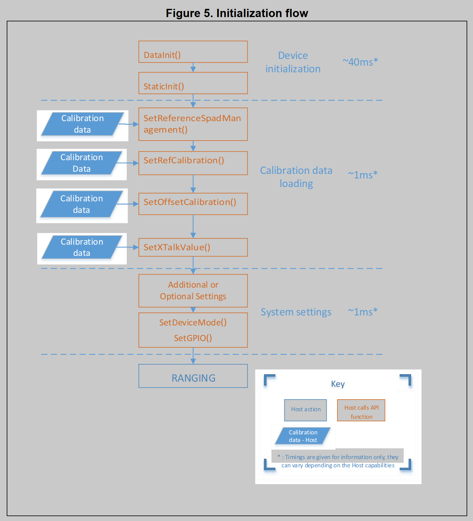
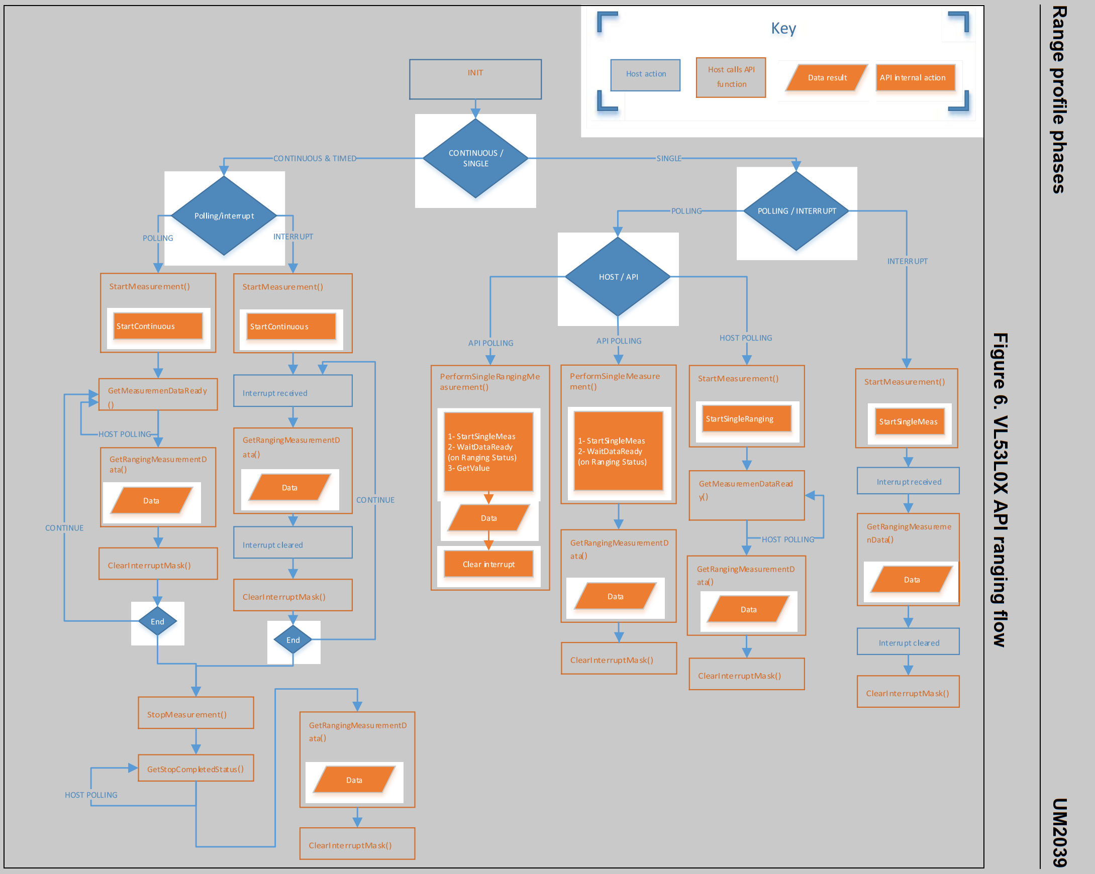
在数据手册中其实结合API函数库给出了模块推荐的工作流程,如下:
首先是初始化流程:

接下来是测量流程:

API使用举例(main.c):
环境:STM32F401CCU6+CubeMX+HAL
在100Hz定时器中进行测量,并将测量标志位置一,然后在主循环中将获得的测量数据使用串口打印出来。
/* USER CODE BEGIN Header */
/**
******************************************************************************
* @file : main.c
* @brief : Main program body
******************************************************************************
* @attention
*
* <h2><center>© Copyright (c) 2021 STMicroelectronics.
* All rights reserved.</center></h2>
*
* This software component is licensed by ST under BSD 3-Clause license,
* the "License"; You may not use this file except in compliance with the
* License. You may obtain a copy of the License at:
* opensource.org/licenses/BSD-3-Clause
*
******************************************************************************
*/
/* USER CODE END Header */
/* Includes ------------------------------------------------------------------*/
#include "main.h"
#include "i2c.h"
#include "tim.h"
#include "usart.h"
#include "gpio.h"
/* Private includes ----------------------------------------------------------*/
/* USER CODE BEGIN Includes */
#include "stdarg.h"
#include "stdio.h"
#include "vl53l0x_api.h"
/* USER CODE END Includes */
/* Private typedef -----------------------------------------------------------*/
/* USER CODE BEGIN PTD */
/* USER CODE END PTD */
/* Private define ------------------------------------------------------------*/
/* USER CODE BEGIN PD */
/* USER CODE END PD */
/* Private macro -------------------------------------------------------------*/
/* USER CODE BEGIN PM */
#define log UART_printf
/* USER CODE END PM */
/* Private variables ---------------------------------------------------------*/
/* USER CODE BEGIN PV */
VL53L0X_RangingMeasurementData_t RangingData;
VL53L0X_Dev_t Dev = {
.I2cHandle=&hi2c1,
.I2cDevAddr=0x52
};
volatile uint8_t TofDataRead;
/* USER CODE END PV */
/* Private function prototypes -----------------------------------------------*/
void SystemClock_Config(void);
/* USER CODE BEGIN PFP */
int UART_printf(UART_HandleTypeDef *huart, const char *fmt, ...);
VL53L0X_Error re = 0;
/* USER CODE END PFP */
/* Private user code ---------------------------------------------------------*/
/* USER CODE BEGIN 0 */
/* USER CODE END 0 */
/**
* @brief The application entry point.
* @retval int
*/
int main(void) {
/* USER CODE BEGIN 1 */
uint32_t refSpadCount;
uint8_t isApertureSpads;
uint8_t VhvSettings;
uint8_t PhaseCal;
/* USER CODE END 1 */
/* MCU Configuration--------------------------------------------------------*/
/* Reset of all peripherals, Initializes the Flash interface and the Systick. */
HAL_Init();
/* USER CODE BEGIN Init */
/* USER CODE END Init */
/* Configure the system clock */
SystemClock_Config();
/* USER CODE BEGIN SysInit */
/* USER CODE END SysInit */
/* Initialize all configured peripherals */
MX_GPIO_Init();
MX_I2C1_Init();
MX_TIM3_Init();
MX_USART1_UART_Init();
/* USER CODE BEGIN 2 */
HAL_GPIO_WritePin(GPIOA, GPIO_PIN_15, GPIO_PIN_RESET); // Disable XSHUT
HAL_Delay(20);
HAL_GPIO_WritePin(GPIOA, GPIO_PIN_15, GPIO_PIN_SET); // Enable XSHUT
HAL_Delay(20);
HAL_NVIC_DisableIRQ(TIM3_IRQn);
re = VL53L0X_WaitDeviceBooted(&Dev);
log(&huart1, "%d\n", re);
re = VL53L0X_DataInit(&Dev);
log(&huart1, "%d\n", re);
re = VL53L0X_StaticInit(&Dev);
log(&huart1, "%d\n", re);
re = VL53L0X_PerformRefCalibration(&Dev, &VhvSettings, &PhaseCal);
log(&huart1, "%d\n", re);
re = VL53L0X_SetRefCalibration(&Dev, VhvSettings, PhaseCal);
log(&huart1, "%d\n", re);
re = VL53L0X_PerformRefSpadManagement(&Dev, &refSpadCount, &isApertureSpads);
log(&huart1, "%d\n", re);
re = VL53L0X_SetDeviceMode(&Dev, VL53L0X_DEVICEMODE_CONTINUOUS_RANGING);
log(&huart1, "%d\n", re);
re = VL53L0X_StartMeasurement(&Dev);
log(&huart1, "%d\n\n", re);
HAL_NVIC_EnableIRQ(TIM3_IRQn);
/* USER CODE END 2 */
/* Infinite loop */
/* USER CODE BEGIN WHILE */
HAL_TIM_Base_Start_IT(&htim3);
while (1) {
if (TofDataRead == 1) {
log(&huart1, "Measured distance: %i\n\r", RangingData.RangeMilliMeter);
TofDataRead = 0;
}
/* USER CODE END WHILE */
/* USER CODE BEGIN 3 */
}
/* USER CODE END 3 */
}
/**
* @brief System Clock Configuration
* @retval None
*/
void SystemClock_Config(void) {
RCC_OscInitTypeDef RCC_OscInitStruct = {0};
RCC_ClkInitTypeDef RCC_ClkInitStruct = {0};
/** Configure the main internal regulator output voltage
*/
__HAL_RCC_PWR_CLK_ENABLE();
__HAL_PWR_VOLTAGESCALING_CONFIG(PWR_REGULATOR_VOLTAGE_SCALE2);
/** Initializes the RCC Oscillators according to the specified parameters
* in the RCC_OscInitTypeDef structure.
*/
RCC_OscInitStruct.OscillatorType = RCC_OSCILLATORTYPE_HSE;
RCC_OscInitStruct.HSEState = RCC_HSE_ON;
RCC_OscInitStruct.PLL.PLLState = RCC_PLL_ON;
RCC_OscInitStruct.PLL.PLLSource = RCC_PLLSOURCE_HSE;
RCC_OscInitStruct.PLL.PLLM = 25;
RCC_OscInitStruct.PLL.PLLN = 168;
RCC_OscInitStruct.PLL.PLLP = RCC_PLLP_DIV2;
RCC_OscInitStruct.PLL.PLLQ = 4;
if (HAL_RCC_OscConfig(&RCC_OscInitStruct) != HAL_OK) {
Error_Handler();
}
/** Initializes the CPU, AHB and APB buses clocks
*/
RCC_ClkInitStruct.ClockType = RCC_CLOCKTYPE_HCLK | RCC_CLOCKTYPE_SYSCLK
| RCC_CLOCKTYPE_PCLK1 | RCC_CLOCKTYPE_PCLK2;
RCC_ClkInitStruct.SYSCLKSource = RCC_SYSCLKSOURCE_PLLCLK;
RCC_ClkInitStruct.AHBCLKDivider = RCC_SYSCLK_DIV1;
RCC_ClkInitStruct.APB1CLKDivider = RCC_HCLK_DIV2;
RCC_ClkInitStruct.APB2CLKDivider = RCC_HCLK_DIV1;
if (HAL_RCC_ClockConfig(&RCC_ClkInitStruct, FLASH_LATENCY_2) != HAL_OK) {
Error_Handler();
}
}
/* USER CODE BEGIN 4 */
void HAL_TIM_PeriodElapsedCallback(TIM_HandleTypeDef *htim) {
if (htim3.Instance == TIM3) {
VL53L0X_GetRangingMeasurementData(&Dev, &RangingData);
// VL53L0X_ClearInterruptMask(&Dev, VL53L0X_REG_SYSTEM_INTERRUPT_GPIO_NEW_SAMPLE_READY);
TofDataRead = 1;
}
}
int UART_printf(UART_HandleTypeDef *huart, const char *fmt, ...) {
va_list ap;
va_start(ap, fmt);
int length;
char buffer[128];
length = vsnprintf(buffer, 128, fmt, ap);
HAL_UART_Transmit(huart, (uint8_t *) buffer, length, HAL_MAX_DELAY);
va_end(ap);
return length;
}
/* USER CODE END 4 */
/**
* @brief This function is executed in case of error occurrence.
* @retval None
*/
void Error_Handler(void) {
/* USER CODE BEGIN Error_Handler_Debug */
/* User can add his own implementation to report the HAL error return state */
__disable_irq();
while (1) {
}
/* USER CODE END Error_Handler_Debug */
}
#ifdef USE_FULL_ASSERT
/**
* @brief Reports the name of the source file and the source line number
* where the assert_param error has occurred.
* @param file: pointer to the source file name
* @param line: assert_param error line source number
* @retval None
*/
void assert_failed(uint8_t *file, uint32_t line)
{
/* USER CODE BEGIN 6 */
/* User can add his own implementation to report the file name and line number,
ex: printf("Wrong parameters value: file %s on line %d\r\n", file, line) */
/* USER CODE END 6 */
}
#endif /* USE_FULL_ASSERT */
/************************ (C) COPYRIGHT STMicroelectronics *****END OF FILE****/
注意事项
- 设备初始化的时候不要开中断!!!
- 注意XShut的连接方式,如果和主设备连接了,则需要在测量之前进行唤醒操作。
关于API的移植
挖坑,以后填......
